To download a printable version of this article (AdjustingSander.pdf), click here
We have a Logan Precision Sander Elite Model F200-2 disk sander. It improves our picture frame miters to a “perfect 45°” after cutting the moulding to size on our miter saw. To maintain such perfection requires due diligence and occasional adjustment.
How Do You Know When It’s Time To Adjust Your Sander?

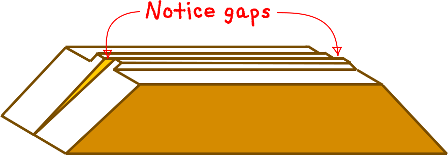
| A. | You may notice that when you put your frames together, there is a small gap between the pieces of moulding either on the inside of all four corners or the outside of all four corners. If some corners have gaps on the inside and some have a gap on the outside, you have other problems. |
| In the figures used in this article, the symptoms have been exaggerated for illustration purposes. If the condition of your sander gets this bad without you noticing, you may want to consider another profession or hobby. | |
| B. | When you are comparing the lengths of opposite pieces, and you have them side by side with the miters face up and their backsides touching, you may notice by running your finger over the miter that they are the same length on one end of the miter but not the other, or that one piece of moulding is higher at one end of the miter and the other piece is higher at the other end. |

In either of these cases, it’s time to adjust your sander.
But What About The Miter Saw?
The miter saw may also need adjustment, but that would have minimal impact on your finished frames. Even if the miter cut angle were wrong, the sander would correct that problem. Of course, it would take more sanding to fix, which besides taking more time and effort, could even result in your frame becoming too small. So check your saw periodically and correct it according to the manufacturer’s instructions. I currently have no improvements or suggestions for that process. An indication that the miter saw needs adjustment would be if, as you are sanding the miter, sawdust builds up on top of one side of the moulding faster than it accumulates on the other. If it takes too many turns of the sander wheel to perfect the edge, that could also be a clue (or it could be time to change the sandpaper).
How To Adjust The Sander
Logan’s simple instructions for adjusting the sander are on the last page of the 4-page manual (available at www.logangraphic.com). They should work almost as well as my plan if you are willing to remove the sandpaper (as required by Step 1).
Adjustment 45°
- Remove sand paper
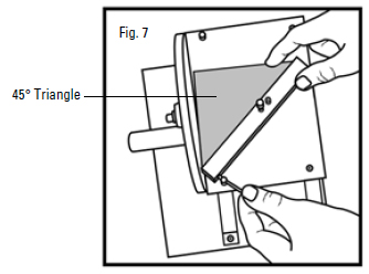
- Place the 45˚ square flat against the wheel and up against bar (Fig. 7). Look for gaps against the bar.
- Adjust the bar using adjustment wrench until gap disappears.
When I don’t remove the sandpaper disk, the technique doesn’t work as well. So I’ve come up with an alternate set of instructions:
-
Put miter cuts on both ends of two long scrap pieces of your widest moulding.
-
When you sand a piece of moulding, each end will use a different side of the sander. Call one side of the sander “A” and the other “B”. As you sand the two pieces of moulding, mark the back of each end of each piece with the side of the sander used (A or B).
-
Find a good right angle, either in a reliable carpenter’s square or using other methods.
-
Flip one of the pieces of scrap moulding upside down so you can join Corner “A” on both pieces to make a 90˚ (right) angle. Flipping is very importantwhy.
-
Put one piece of moulding along one edge of the reference angle (carpenter’s square) and slide the reference toward the second moulding until it just touches at one end or the other (if it touches at both ends, you are finished with Side A – skip ahead to Step 7). Measure the error gap (I like millimeters only because they are so small) at the end of the moulding that’s away from the reference line. Then measure the length of that piece of scrap moulding (using the same units of measurement).
-
Divide the error you measured in the last step by the length of the moulding that you measured and multiply by 25,000.
Your result will be the number of degrees you need to turn the adjustment screw. If the error gap was at the corner, the angle is too large. Turn the screw counterclockwise to shorten the exposed screw. Conversely, if the error gap was at the end of the moulding, the angle is too small. Then you have to turn the adjustment screw clockwise to push it out more. After making the adjustment, you may want to retest. Repeat the process, starting at Step 2 and re-sanding the two corners just used. Before sanding, I recommend drawing a line across the miter cut with a pen or marker and then sanding until the line completely disappears.
-
Repeat this whole process (starting at Step 4) for the other two miters, labeled “B”. Remember, for these two you will be playing with the adjustment screw on the other side of the sander.
-
That’s all there is to it. Congratulations.
Math Warning: a quick note about trigonometry (OPTIONAL)!
This process concerned angles, not distances, but since angles are harder to measure with any precision, we had to convert. When you take the ratio of the two perpendicular sides (the sides that are 90° apart) of a right triangle containing the angle you are interested in, that’s called the tangent of that angle. You can have a good calculator app on your phone find it for you (for my Droid, I found RealCalc Plus by Quartic Software at the Play Store and was happy to pay $3.50. There are plenty of other options, though).
The error angle you measured (indirectly) was actually twice as large as the real error. One problem is that the tangent curve is not generally a straight line, which means that the tangent of twice some angle is not the same as twice the tangent of that angle. That’s why the normal procedure would be to convert to angles, do the adding, subtracting, or multiplying, and then convert back to distances we can measure again. We were able to use the small angle exception, however. It turns out that for angles less than, say 10°, the tangent curve IS pretty straight, and the error introduced by taking our shortcut isn’t worth worrying about. That’s what we did with the error angle, and that’s why the problem was so easy. That’s your math lesson of the day week month. Let’s get back to work.

Leave a Reply