revised 12/31/2021

This article is the first of the “Weird Wood” seriesintro. In it we show how to build a picture frame using four strips of moulding that aren’t all the same width. Figure 2 uses a different width for each piece of moulding. But we were forced to use only three different sizes in our test frames because I couldn’t find four different sizes in the same moulding family.
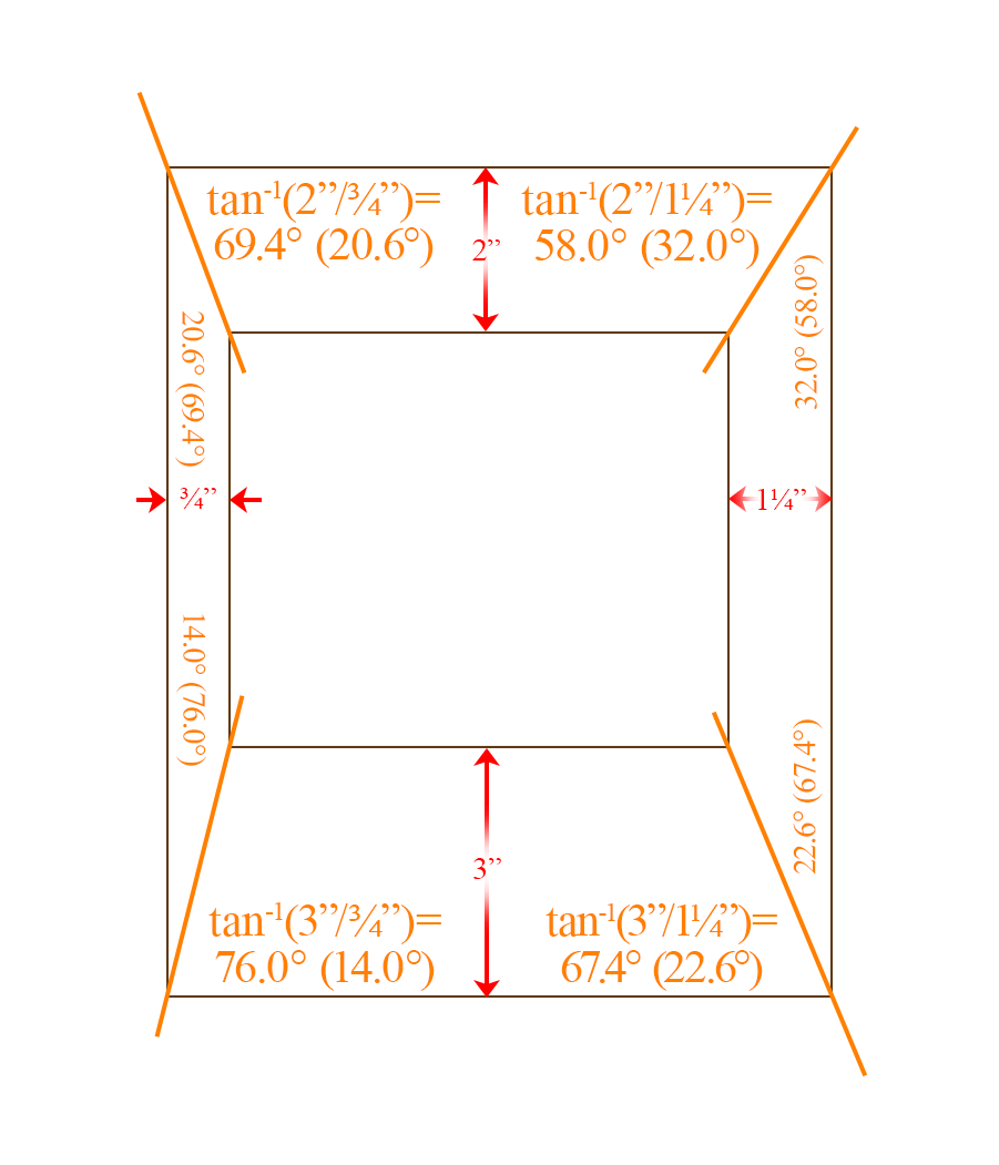
First The Math
Warning: This discussion includes a little trigonometry. Do Not Panic! It’s not as bad as it sounds.
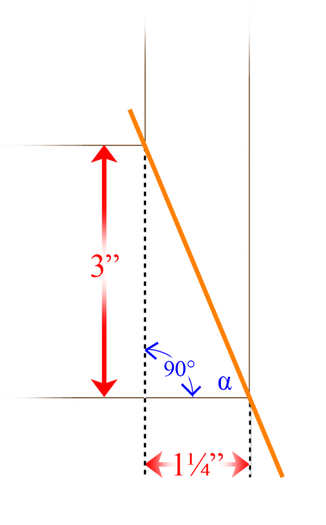
Definition of “Tangent”
(Skip ahead To next paragraph if you still remember this):
There are three sides to any right triangle (a triangle with a 90° corner). I will call the ones touching the right (90°) angle the height and the width. The last, longest side is the hypotenuse. It is opposite the right angle. You can use the ratio of the lengths of any two of these sides to find the size of the other two angles.
Each possible ratio has a name, but we are only interested in one of them today. Probably the most common ratio and the one we will be using is called the tangent. The tangent is defined as the ratio between the height (the length of the side opposite the angle you are interested in) and the width (the length of the shorter of the two sides that create that corner that you are interested in).
You would use your calculator (or phone app) to find the angle corresponding to that tangent. On your calculator, the tangent is abbreviated “tan.” If you enter 45 (degrees are assumed) and hit the “tan” button, you will get 1 because, for a 45° angle, the height is the same as the width, so their ratio is 1. To go the other way (to find the angle), like we are trying to do, we need the inverse of the tangent. Look for the “tan-1” button. It could be the same button, in which case you may need to hit a (yellow) shift or second-function key, and then hit the “tan” button).
If you want to know the angle of corner α in Figure 3 above, you would calculate its tangent by dividing the height (3 inches) by the width (1¼ inches) to get 2.4. Then we hit the inverse tangent button(s) to get 67.380135…. (the calculator is obligated to give you eight or more digits – that doesn’t mean they all mean anything. In Figure 2, I rounded that answer to 67.4 degrees, and even that third digit should be suspicious.)
The Process
All you have to do is take the ratio between the widths of your two moulding pieces and take the inverse or arc-tangent to get the angle. Here are a few things you need to remember:
- Which angle – the tangent gives you the angle that was touching the side whose length was used for the denominator (the width, which would be the second number in the division). The simplest way (but certainly not the only way) to get the other non-90° angle is just to subtract the first from 90° (since the two angles are complementary). Also, remember that if the tangent were greater than one, the angle would be larger than 45°; if it was supposed to be a smaller angle (less than 45°), you might have divided the two lengths in the ratio backward. Don’t worry, you just found the complementary angle, and all you have to do to get the right answer is subtract what you got from 90.
- It is up to you to keep track of whether the angle you are cutting should be to the left or the right. Making a drawing of your frame design might help. To be useful, the drawing doesn’t even need to be that good. A drawing could also tell you if you calculated the complement (the other angle in that corner (for the other piece of moulding)).
- Your saw may be measuring the angle backward. My miter saw calls a cut perpendicular across the board 0°, not 90°. If that’s the case, just subtract the angle you calculated from 90.
As an exercise, go ahead and check the rest of my calculations in Figure 2. 😁
Make The Cuts
There is more than one way to make these cuts and more than one set of tools to help you. Which set of tools you should use will depend on such things as how much of this work you intend to do, your skill set, what your budget is, and what tools you already have on hand.
Looking through the Framers’ Corner, the forum of the Professional Picture Framers Association, I found recommendations for the following tools for this application:
- WEN 10412 12-Piece Steel Angle Gauge Block Set with Case
- Incra MITER1000SE Miter Gauge Special Edition With Telescoping Fence and Dual Flip Shop Stop.
(The Amazon.com descriptions are only used here as a reference. Although frequently competitive, Amazon isn’t always the only or the best place to buy something.)
You would only need one of these (if any), not both.
Our workshop includes all of the tools listed in www.BeeHappyGraphics.com/about.html#BruceEquip, along with several other regular hand & power woodworking tools that Nancy has accumulated over the last several decades. For this project, I used our compound miter saw, but not without complications.
A Problem
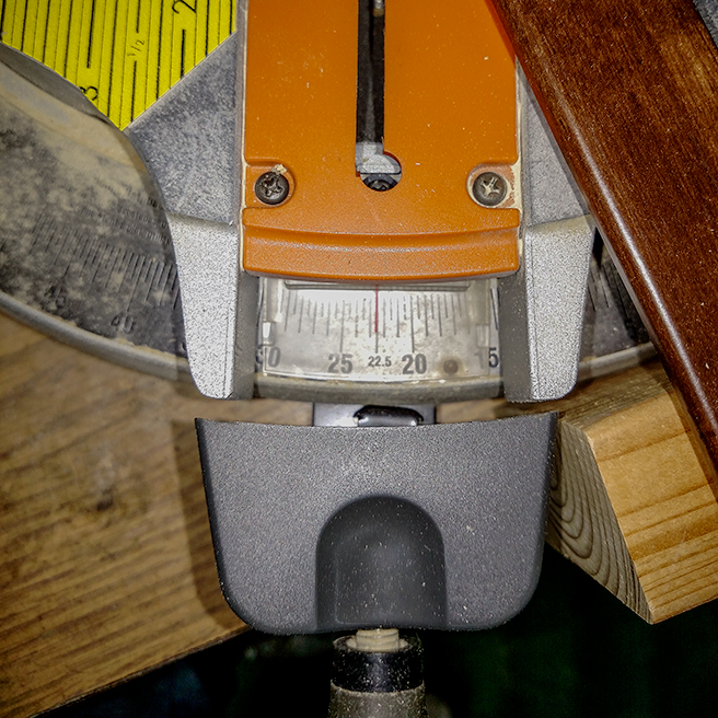
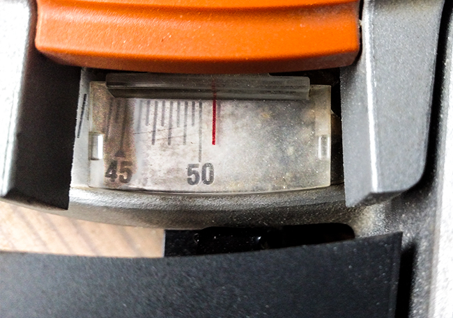
The precision on this saw looked fine; you should be able to get within ¼° of your target. The first picture (Image 4A) shows me trying for 22.6° (one of the angles between the 3″ and a 1¼” moulding). But after cutting the 3″ piece, I ran into problems trying to cut the complementary angle (67.4°) on the 1¼” piece, as shown in Figure 4B.
I am not claiming that mine was the best path to reach our goal. In fact, I would love to see your ideas in the comment section about how to improve my techniques.
How I Did It
-
Working with one corner at a time, I cut both pieces of moulding square just a tad longer than their overall/outside measurement according to your diagram (you will see why in Step 4). If you don’t already have one, this is also when you would put a perfectly square cut on the alignment block you’ll see in Figure 7 to the left of the moulding. I grabbed a 2″ by 4″, but the wider your piece the better.
-
I set the saw for the smaller of the two complementary angles, rechecking my diagram to confirm whether it should be to the left or right. In the setup shown below, the 3″ moulding would be clamped to the right of the blade.

-
I made the cut.

Figure 6 -
Without adjusting the angle of the saw, I set up the second cut. I positioned my (newly cut) alignment block to the left (opposite the side we placed the moulding for the cut (in Step 2)) so that I could also place the 2″ moulding to the left of the blade and perpendicular (at a right (90°) angle) to the miter saw fence. After clamping down the alignment block, I added a support block to the right of the moulding to keep it in place. I could still move the moulding in or out to position the cut. As you can see, I needed to precut this piece of moulding to keep it from extending too far into the aisle and getting in my way. Another reason is explained in Step 6.
-
I made the cut.

Figure 7
For those who noticed that the color of the moulding in Figure 6 was different than in Figure 7, I had to make two different frames while doing research for this article
- to confirm and refine my techniques and
- because I didn’t get enough pictures the first time.
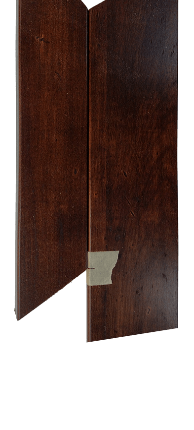
- Always check your work. Since you precut each piece of moulding a little longer than necessary, consider this first cut on each piece a test cut. See if the two pieces match up as expected. If, when you put the two pieces of moulding together, the miter edge on one piece is longer than the other, that is the angle that should have been larger. The angle on the other piece of moulding should have been smaller (by the same amount).
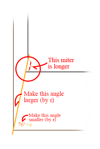
Figure 9 shows the second setup from the right side. If you look close, you might notice that I didn’t cut enough to make a sharp corner and needed to recut.
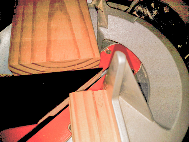
- Moving to the next corner, I precut another piece of moulding and repeated Steps 2 through 6. Now that both angles are correct for the second piece of moulding, you can recut its last miter if necessary to get the length right.
- I repeated Step 7. When both angles are correct on the third piece of moulding, recut the last miter on that piece as necessary to get the length right.
- I repeated Step 7 one last time. When both angles are correct on the fourth piece of moulding, I used the second piece of moulding to mark the length of the fourth piece by matching the inside edges, as shown in Figure 10. Similarly, I used the third piece of moulding to mark the length of the first piece.
[Update 3/18/2023: I just saw a short video by Casey Finn on Instagram that appears to makes my setup look silly. Check out Angled Miter Cut. I have not yet tested her setup. But I have tried other solutions, as discussed in “How To Join Mouldings With 30° & 45° Bevels”. (You can find the link in the comments section below).]
Finishing
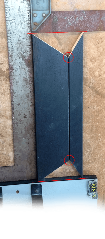
As with my regular frames, I would next need to make sure the inner lengths on opposite pieces of moulding matched. The outer lengths must match as well. Figure 11 shows a way to check if the outside and inside corners of the opposite sides match using two carpenter squares (or equivalent).
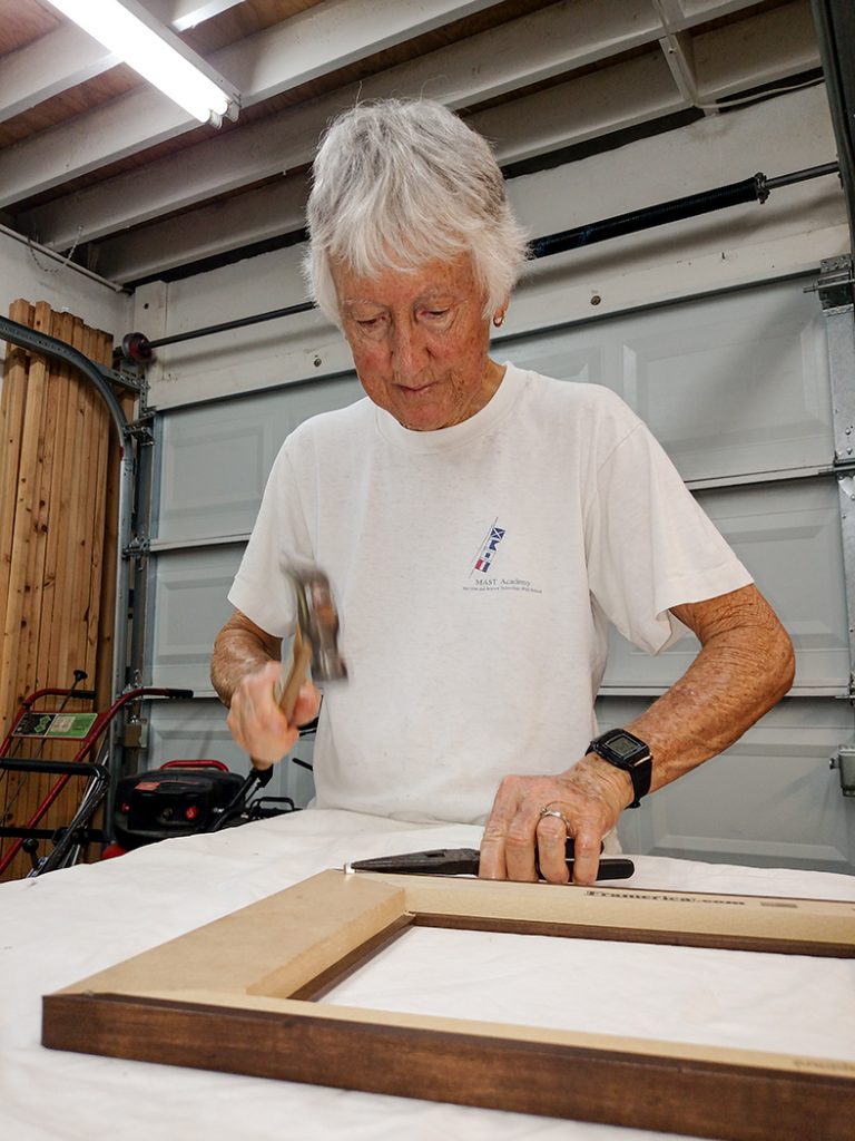
Some of the tools we usually use to finish putting the frame together, namely our Logan Precision Sander and Logan Pro Joiner, are worthless for this application. After gluing (and clamping the pieces together until dry), we had to pound the V-nails in by hand. (Interestingly, the simpler Logan Studio Joiner can be adapted).
The Back Side
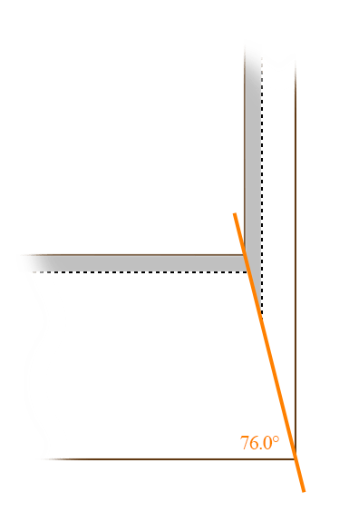
For completeness, the left figure below shows how the backside of the lower-left corner would look. The gray section represents the rabbet, the equal-width (¼”) cut-out that holds the picture’s glass, mats, image, and backing inside the frame. You might be surprised to see a triangular notch in this rabbet in the corner along the miter cut. This notch does not affect the functionality of the rabbet.
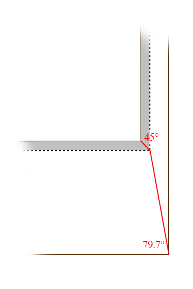
To solve this “problem”, however, you could make a compound cut. Cut 45° in from the inner edge to the edge of the rabbet. Cut 79.7° in from the outer edge to the same point, as shown in Figure 14. (As an exercise, you can check my math on these angles also.) But there is really no need to make these cuts. If the gray were to represent an equal-width feature on the front of the moulding, it might be worthwhile to take the extra trouble. Otherwise, don’t even think about it.
The End
Congratulations, you now have a fancy new picture frame. Of course, you still need to print the picture, cut mat(s) and backing, mount the picture to same, cut glass, assemble the pieces without showing any annoying specks, and apply a dust cover and hanging hardware. But all of that is beyond the scope of this article. Good luck!
As mentioned, this article is just the beginning of a series about “Weird Wood” that I announced months ago. Next, we will look at handling moulding that is not uniform width. You won’t find this moulding in any store; it is only an exercise to prepare you for our final project. But if it stimulates your creativity, that’s not always a bad thing. Stay tuned, and thanks for reading! Your comments are welcome and appreciated.
Leave a Reply