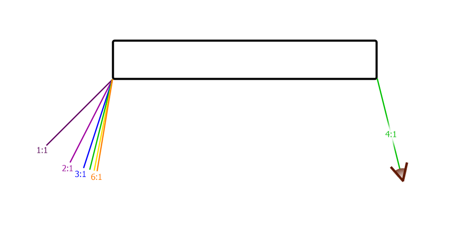
When describing our canvas gallery-wrap optionslink, we mention that the technique we use, the digital stretch wrap, creates an optical illusion. For any given amount of stretch, there is a particular “illusion angle” at which the sides look like an unstretched and uncompressed continuation of the frontthe math. Figure 1 shows that angle for various stretch ratios (we have traditionally used a 4:1 ratio). Notice that the angle is to the side of the image at all stretch ratios. So only one edge (or at most two adjacent edges) could be visible at any time.

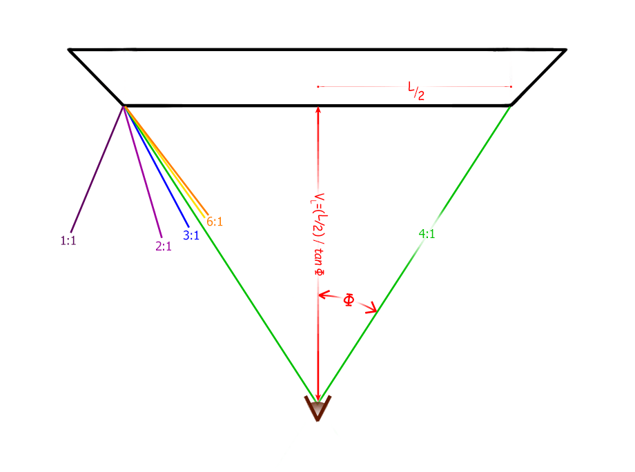
Once we started using bevel-edged frames for our gallery wrapsannounced, the inevitable question was “how would that affect the illusion angle?”. As can be seen in Figure 2, when the edge of the frame shifts out to a 45° bevel, the illusion angle shifts accordinglymore math. With even a small amount of stretching, the angle shifts toward the front of the image instead of the side. This, in turn, means that you can commonly see both of the opposite edges of the image simultaneously.
That means that there is a point where the illusion angle lines from both sides cross. At that point, both sides will look like a continuation of the front at the same time. For these two opposite sides, this would be the illusion viewing distance (IVD). As you move further away from the image, the edges will look more stretched. As you move closer to the image, the edges will look more compressed, until you reach the point at which they disappear entirely. Figure 2 goes on to show how to determine the illusion viewing distance, given the illusion angle Φ.

With a beveled edge, it is possible to see the illusion on all four edges simultaneously, instead of just one edge. This sets up the possibility that you can make all four edges look like a continuation of the front image at the same specific distance. I call this the optimum illusion viewing distance (OIVD). As you see in Figure 2, the illusion viewing distance depends on the length (or width) of the image front. If the width is not the same as the length, the illusion viewing distance for the side edges will be different from the top & bottom edges if you stretch them the same amount.
If you are using the same moulding on all four sides, you need to stretch the short edges (at the ends of the longer sides) more than you stretch the long edges (at both ends of the shorter sides) to get both illusion viewing distances to be the same. The more severe the aspect ratio, the more it makes a difference. If the aspect ratio is close to one (meaning the length is about the same as the width), you probably don’t need to worry about the difference. We are still perfecting our techniques, but so far, we’ve been using a 30° bevel whenever we can. We go to a 45° bevel for our panoramas, where the aspect ratio is greater than about 2:1.
Next, I’ll walk you through a set of calculations to find the appropriate stretch ratios and optimal illusion viewing distance for a project.
An Example
The Math
Suppose we wanted to print a panorama that was 18″ high by 84″ wide on the front face. With that aspect ratio (4.667:1), we will use the 45°-beveled moulding. Following tradition, I will start with a 4:1 stretch on the left and right edges. Using the formula toward the bottom of Finding the Angle of the Illusion For Beveled Frames,
\( \begin{array}{r c l}
\tan \theta & = & \frac{\sin 45^\circ – \frac{1}{S}}{\cos 45^\circ} \\
\theta & = & \tan^{-1}(1 – \frac{\sqrt{2}}{4}) \\
& = & 32.9^\circ
\end{array} \)
(or in this case, we could have just looked it up in the table just below that formula).
Then, from Figure 2,
\begin{array}{r c l}
V_{L} & = & \frac{L / 2}{\tan \theta} \\
V_{84} & = & \frac{84 / 2}{\tan 32.9^\circ} \\
& = & 64.92″
\end{array}
Now, make V18 = V84. To find how much you need to stretch the other two edges, you need to find the illusion angle based on the common illusion distance by reworking the equation in Figure 2:
\begin{array}{r c l}
\tan \phi & = & \frac{W / 2}{V_{W}} \\
& = & \frac{18 / 2}{64.92} \\
& = & 0.13863 \\
\phi & = & 7.89^\circ
\end{array}
Finally, we find how much we need to stretch the last two edges to get that illusion angle:
\begin{array}{r c l}
S & = & \frac{\cos \phi}{\sin (45^\circ – \phi)} \\
& = & 1.6418
\end{array}
Another approach would be to start with a desired optimal illusion viewing distance and use it to calculate both stretch ratios. The problem with this approach is knowing in advance what viewing distances would be appropriate. On our webpage Guidelines for Art Exhibition in the Home and Office, we discuss viewing distance only as it relates to hanging height.
The Process
We discussed how we stretched our non-beveled gallery-wrap edges in How We Digitally Stretch Our Gallery-Wrap Edges Before Printing (Hereafter called “the Stretch article”). The preparation process discussed there is almost the same for our new beveled edges. Next, we will walk you through that. The moulding preparation and canvas stretching processes are a different story – again, one beyond the scope of this article.

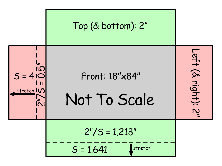
Using the above example, we want the front of our image to be 18″ by 84″. We also want an extra 2″ of stretched image on each side. But instead of automatically adding ½ inch for each edge before cropping, you need to divide the final width of each edge (2″) by its new-found stretch factor. As shown in Figure 3, you would still add ½ inch for each of the left and right edges for a total width of 85″ on the crop. But the top and bottom edges would each be 1.218″, for a total height of 20.436″. Remember to delete cropped pixels when you crop. As in Step 2 of the Stretch article, you would then save it as a new file.
As in Step 3 of the Stretch article, you would place guides 1.218″ in from the top and bottom edges and 0.5″ in from the left and right edges of the image. You would enlarge the canvas to 24 “x88” to reflect the size of the image with each edge stretched. Then you would stretch each corner and edge individually using the distort transform. Finally, continue at Step 6 of the Stretch article to finish up.
That’s it. Congratulations.
Below is our image Cedar Keys Lighthouse, one of our first panoramas using these principles.

What’s Next
The next steps would be to show how we make our beveled moulding by ripping an angled cut from the bottom edge of the store-bought moulding [see How To Make Our Beveled Stretcher Bars]. Then we could show how we make the frame, and maybe even how we stretch the canvas around the corners. Those articles could come later this summer. My long-promised articlepromise on how we made a frame out of warped fence pickets will most likely come first. It is already half-finished [see Making A Picture Frame From Dilapidated Fence Pickets].
We are still optimizing our corner folds on the 45-degree bevel. We are also looking at combining 45-degree bevels on our panoramas’ short edges with 30-degree bevels on our long edges. That investigation sort of ties in with the long-promised Weird Wood series. It would be an extension of Using Multiple Moulding Widths In One Frame. But that would be a separate article. It might be a while before we get to that one [see first comment below].
Leave a Reply