Weird Wood – Part 5 of 5
As you may recall, this series began with Working With Weird Wood: Preface. After reading that, you may be asking yourself, “What happened to Parts 2 through 4 of this series”? After all, I did publish the promised preparatory article Thoughts On Mat Layout and Part 1 of the series, Using Multiple Moulding Widths In One Frame. So where is the frame from moulding with straight, non-parallel edges? Or the frame with the wavy inside edge? Or the frame from moulding with curved but parallel edges? I haven’t abandoned them, but they aren’t finished yet. Because of the time that has elapsed already, I decided to go ahead and do this one now. I’ve finished this project and should have all the pictures and notes I need. So here we go!
The Wood
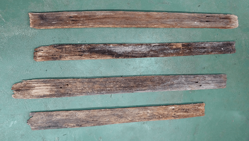
As I mentioned in the preface article, these pickets had been part of Nancy’s friend’s parent’s parents’ farm in northern Florida for as long as anyone can remember. She wanted to know if we could build a picture frame out of them.

This wood was between 2½ and over 3½ inches wide and ½ to ¾ inch thick. As you can see in Figure 2, there were cracks, and the surfaces were not flat, smooth, or parallel. There were some soft spots. The first step was to clean and preserve them.
Wood Preparation
There are plenty of articles covering this part of the process, and I saw no way to improve them. There were no nails or other hardware in these pickets, so I just scrubbed the wood hard a couple of times with a good stiff brush and a solution of Simple Green and water. I was a little concerned about whether they would make it through that process. But if they couldn’t, I probably shouldn’t use them on this project anyway. They made it with only minimal losses. After they dried, I coated them with Minwax Polycrylic Clear Matte, a water-based protective finish, just following the directions.

The Design Process
The Inner Frame
With 3/32” (2.5 mm) thick glass, two 1/16” mats, a 3/16” thick foam board, and a little freeboard for driving the points into the frame, I figured the depth of the rabbet in the frame needs to be over 1/2“. That meant that these boards weren’t going to cut it, so to speak. I decided I needed an inner frame to provide a box for the contents and support the pickets, which would be the outer frame.
After being matted, the original print was 121/2” high by 143/8“, so those will be the inner dimensions of the inner frame (plus less than 3/16” along each side for expansion). Since I want at least a 3/16” lip (this would be the width of the rabbet on conventional moulding), the inside edges of the outer frame will have maximum lengths of 121/8” by 14″. See the note below if you want more of the details going into those dimensions for this example.
The Outer Frame
With those dimensions and the dimensions of the pickets, I used Photoshop for planning and visualization. It is fairly easy to slide boards around virtually, but one challenge is making sure all parts are of the same scale. In the blog article Adding Size-Appropriate Objects To Your Image, I addressed that issue in the first section (Resize One Picture To Match Pixels Per Inch For The Two Subjects) of the first example (A Safe Selfie).
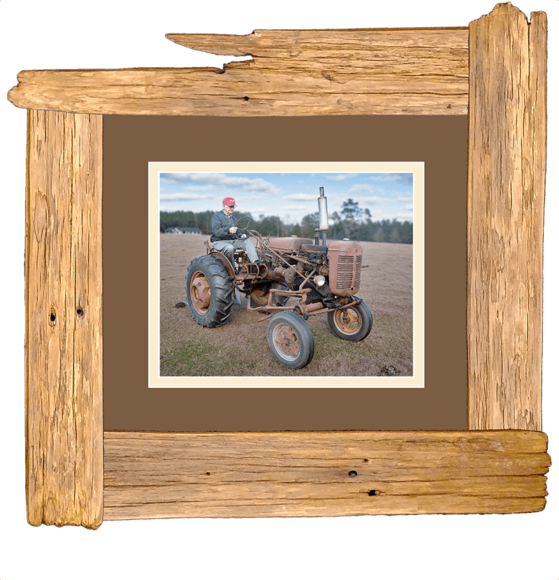
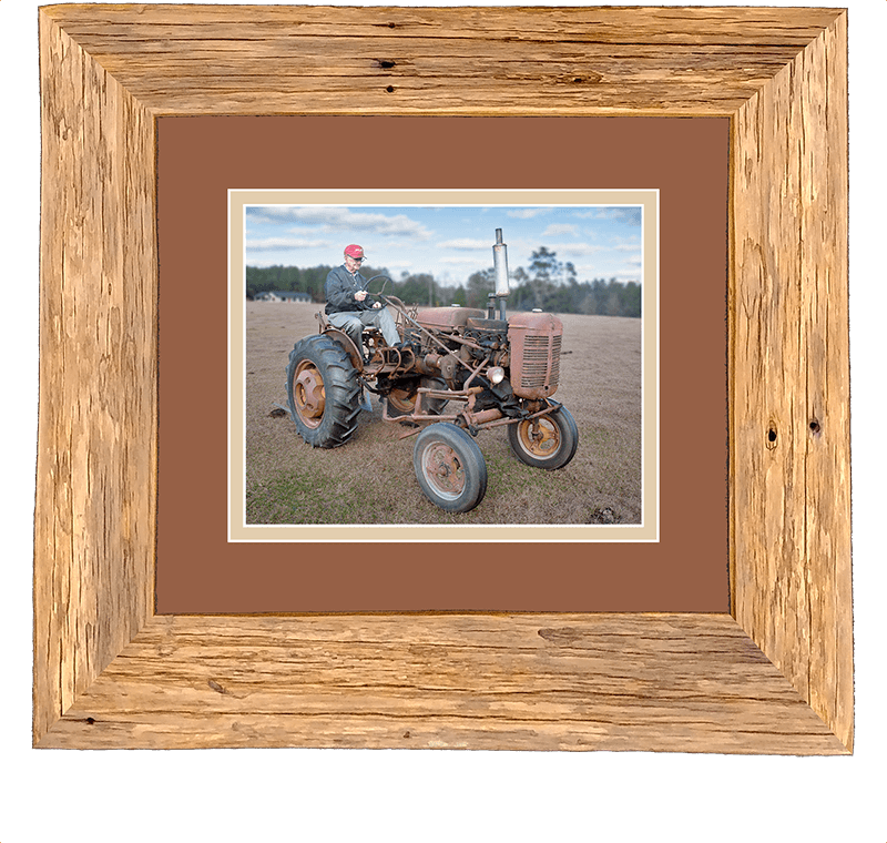
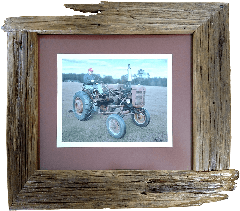
In Figure 4 are a couple of the options I showed our customer: one with all butt joints and one with all miter joints. I was sort of partial to the butt joints; they show off the ruggedness of the wood better. Although non-standard because of the variable thickness of the wood (an issue semi-solved in Using Multiple Moulding Widths In One Frame), the miter joints seemed like they might be too “polished” for this application. The customer went for a hybrid frame with two joints of each type. (See the picture in Working With Weird Wood: Preface or scroll down to see the finished product).
Since there is no rabbet along one edge of this ‘moulding,’ one might be tempted to save wood and make their miter cuts like the leftmost cut (A/B) in the top board in Figure 5, with virtually no scrap. Then one would join A to C, as shown in the leftmost corner sample below that. If the wood is highly variable in appearance, one might still want to make their cuts in the usual fashion. Even if you had to put a small gap between the cuts, as shown between C and D (maybe to be able to utilize both of the ragged ends of a single board), the miter edges would still be closely matched, as shown in the C/D corner to the lower right in Figure 5. Compare the ‘grain’ pattern of the two corners.
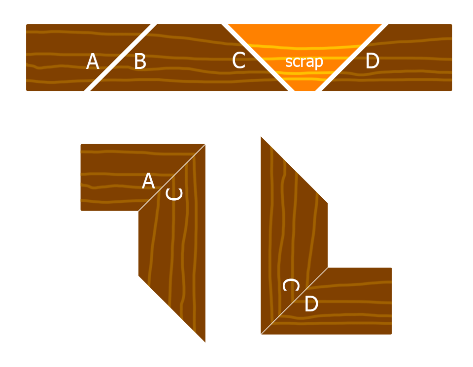
Figure 6 shows examples of these strategies. If the wood is more uniform in appearance, it might not make much difference.
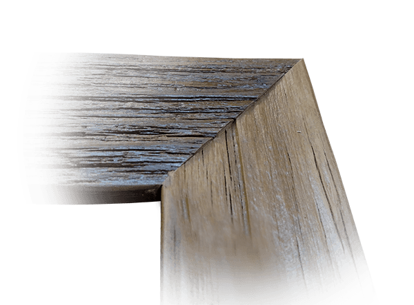
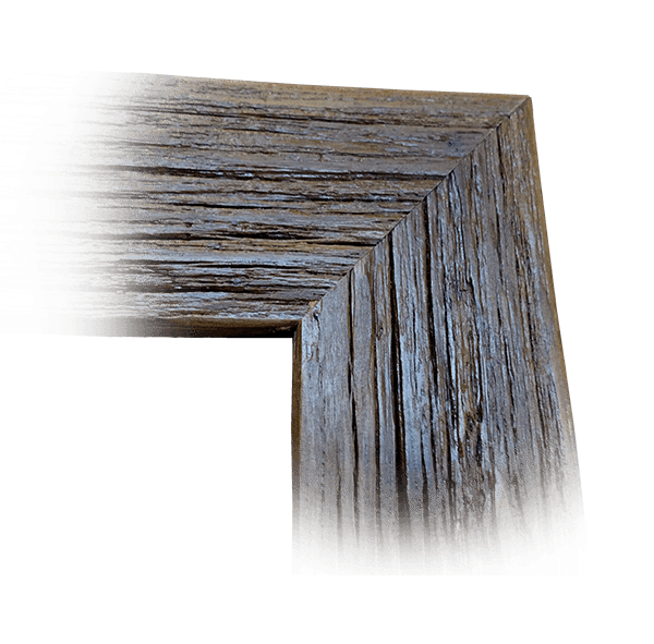
The ‘hybrid’ two-miter-joints-and-two-butt-joint design the customer chose did have advantages. The four pickets measured 35″, 38″, 43″, and 44½”. As discussed, the inside measurements of the frame were 12⅛” (making the outside measurement at least 17¼”) and 14″ (giving an outer length of up to almost 20½”). That means that it was only possible to get two pieces of moulding and their intermediate miter cut out of each board. Using the longest two pickets, I could cut two miter joints to put in opposite corners of the frame. This would leave the ragged end pieces of the two boards to overlap on the remaining corners.
You could be systematic and let the board coming in from the right play through. Or you could let whichever end looked more interesting have the right of way. Both boards were long enough for two adjoining sides with a few inches left over on one end (since we didn’t add a gap between cuts, as shown in Figure 5). Therefore, each non-miter corner had a measured end and one with extra wood. We trimmed the extra wood along the edge of the good end (see Figure 13). The wood you are given to work with may dictate other choices.
Construction
The Inner Frame
I thought ripping a one-by-two (actual dimensions approximately 3/4” by 11/2“) in half on the table saw should be good enough. And so that my measurements didn’t have to be perfect, I made 3/4” the depth. Because of the 1/8” kerf, the width of the resulting moulding was around 11/16“. I measured the desired lengths, measured again, cut the miters, glued the joints, let them dry, then V-nailed them. Then I prepared them to be attached to the outer frame.
How I Attached Inner And Outer Frames

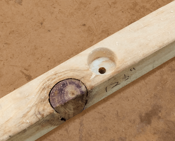
In Figure 7, the upper, lighter-colored piece is the inner frame and the darker bottom part is the outer frame. Some features in that drawing may have been exaggerated and are not to scale. The outer two screws are the ones that hold the outer frame and inner frame together. As in most cases, when you want the screws to be able to bring the two pieces tightly together, the size of the pilot hole you predrill in the underlying piece should have roughly the same diameter as the shaft of the screw (not including the threads). The clearance hole you drill in the upper part should have a diameter slightly larger than the widest diameter of the screw (including threads)explanation. For this project, I used #8 flat-head screws. As shown in Figures 7 and 8A, the holes in the inner frame were countersunk, of course.
Since the outer frame is not perfectly straight, the distance between the outer and inner frame cannot always be zero at these attachment points. That is why I added the stand-off screw to each side of the frame. I thought that one in the center of the board would work in this case instead of one for each attachment screw.
I used a #12 pan-head screw, and ground the point off to give it a better pushing surface. Since the only thing the screw could be gripping was the inner frame, the hole diameter was measured as a pilot hole, not a clearance hole, and was roughly the diameter of the screw shaft (without threads). I countersank the hole halfway through the 3/4” thick board, trying to make sure the screw had enough wood for an effective grip while giving it as much adjustment range as it might need. Figures 8B and 8C show details.
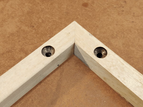
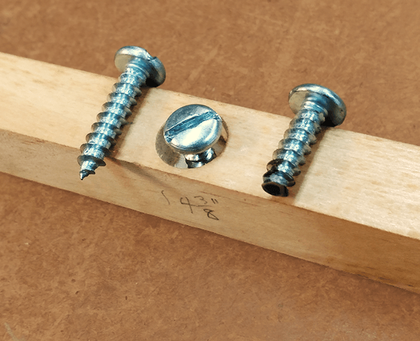
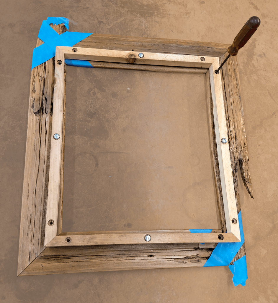
Although it is getting ahead of the narrative, Figure 8D shows the completed inner frame as I am starting to attach it to the outer frame. We will discuss that procedure soon.
The Outer Frame
Measure
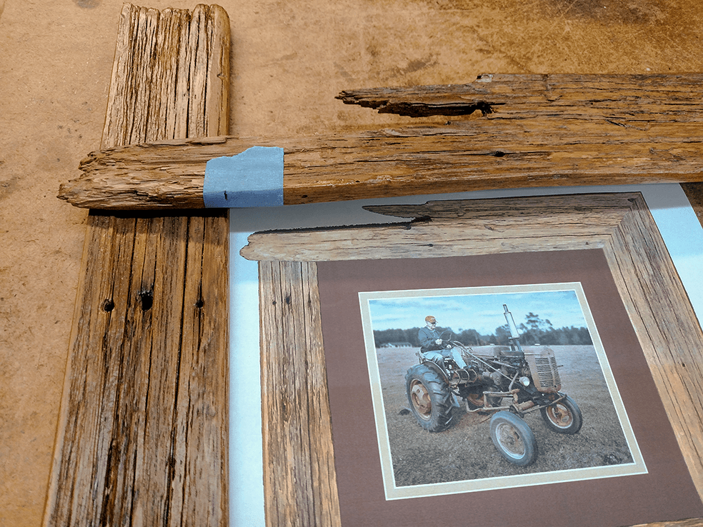
Figure 9 shows the first mark on the inner length of the first board. I used painter’s tape because I didn’t want to put marks on the frame.


Figure 10
Additional measurements and marks are shown in Figure 10 (above). As discussed earlier, the inside length of the long pieces was 14 inches. The top picture shows making that measurement. The middle picture shows measuring the first 45° miter cut. The bottom picture shows measuring the other miter angle for planning purposes. As I will explain in what was supposed to be Part 2 of this series, unless the inside and outside edges of the moulding are perfectly parallel, one should measure the 45° angle from the inside edge instead of the outside edge. And just in case you forget that a 1/8” blade kerf on a 45° angle eats up almost 3/16” of your wood length \( (\frac{1}{8} \sqrt{2}) , \) you don’t really need to get serious about that measurement until after you make the first cut.
Cut Miters
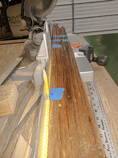
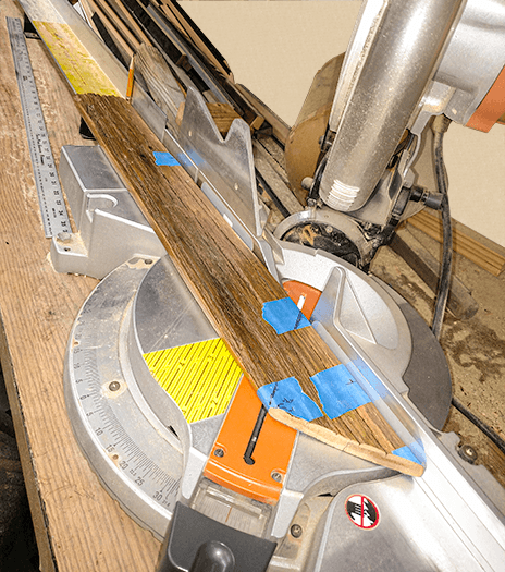
Figure 11A shows how well this picket lines up along the miter saw fence. I was just able to slide a pencil between the fence and the widest part of its bow. That means that as pieces are cut, the alignment could change. I hope to discuss solutions to that problem in Part 3 or 4 of this series. As you can see in Figure 11B, I continued to use that pencil as a spacer for the second cut.
Join Miters
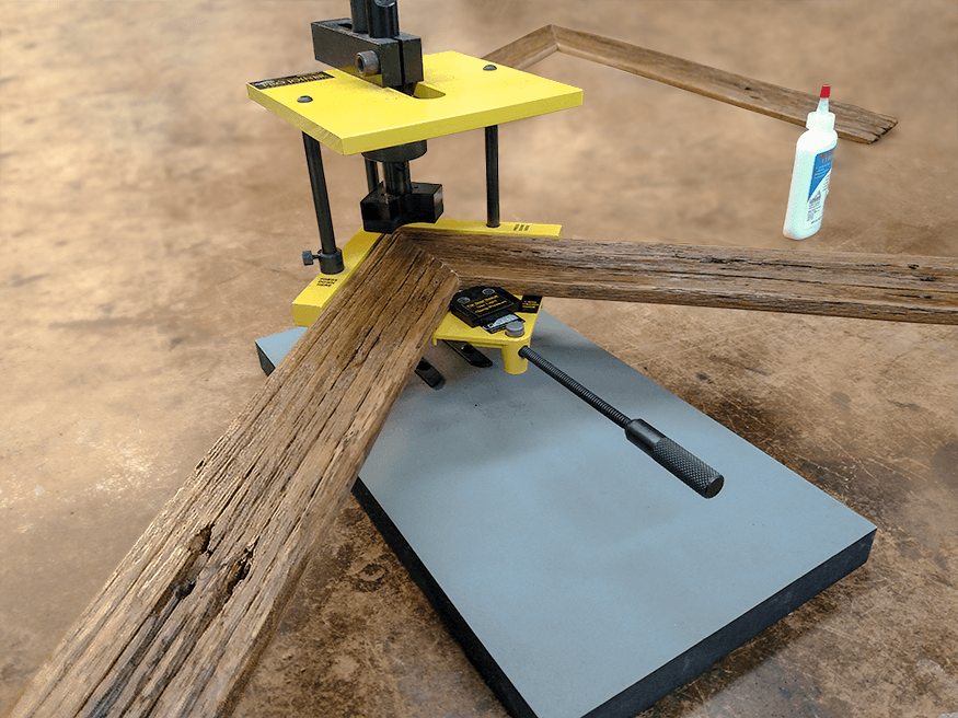
After cutting, we glue the joints, let them dry, and then join them. Figure 12 shows the first miter corner about to be V-nailed. The second mitered corner has already been glued and is in the background.
Measure & Cut Ends For Butt Joints
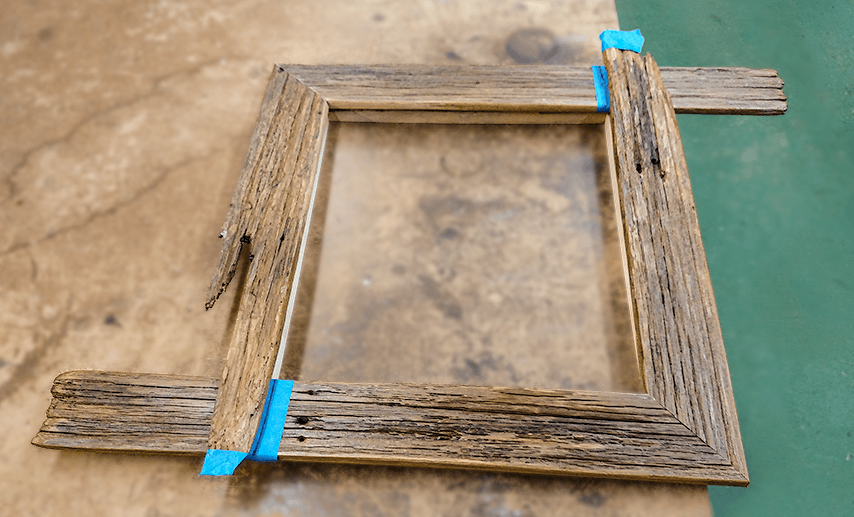
In Figure 13, I placed the two halves of the outer frame in position on top of the inner frame so we could mark the edges to cut for the butt joints.
Figure 14: Cutting for butt joint
In Figure 2, you may have noticed that the edges of the pickets were somewhat rounded. The video in Figure 14 mentions that I deliberately cut the edge at an angle. As Figure 15 shows, putting a slight angle on the cut dramatically reduces the visible gap between the pieces of this joint. (The front of the frame is on top). You may have also noticed how precisely I measured and made those cuts in the video. I felt the resulting tolerances were still good enough to fit the frame’s character. You might also consider a cross lap joint for these corners, in which case you are on your own.

Connect Inner and Outer Frames
Reviewing Figure 8, you can see how we held two frame pieces together with painter’s tape while I marked the screw holes for predrilling. I then drilled those holes and assembled the frame, adjusting the corner attachment screws and the central hold-off screws as necessary.
Problems
While assembling and then placing the glass, we noticed a few problems.
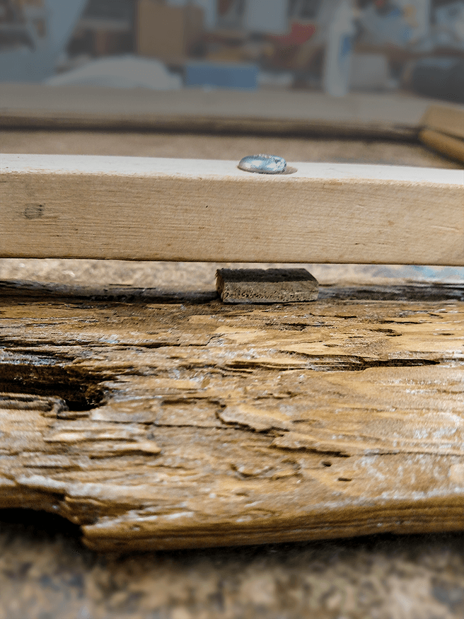
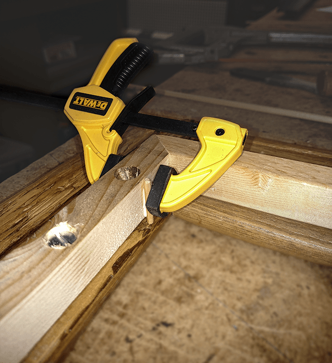
As you can see in Figure 16A, the wood was warped enough to create quite a gap between the inner and outer frame in the middle of one side. This created two problems. First, our stand-off screw wasn’t long enough to touch the outer frame. The correct answer would have been to get a longer screw. Since we didn’t have one on hand, I glued a small scrap piece to the outer frame directly under the screw. That gap also allowed the glass to fall between the two parts. Figure 16B shows where we glued a short dowel to prevent that. The dowel had to have a small enough diameter to fit the limited space between the glass and the edge of the inner glass but be sturdy enough to support the glass. But if one thin dowel wasn’t sufficient, we could have used two (or more).
Between the jaws of the clamp in Figure 16B, you can see that the original countersunk attachment screw hole is empty. The wood underneath that hole turned out to be too soft, so we had to redrill the hole to the left.
Conclusion
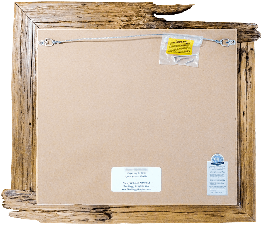
After I completed those hacks, Nancy was able to insert the glass and picture components, sans dust or dirt specs. (That typically takes more than one try.) Then she drove in the points to hold them in place. Finally, she added the dust cover, hanging wire, and labels to complete the job.
And that’s all there is to it. If I wasn’t clear enough on anything, or if I left out any steps, or if you have any additional questions, or if you can add anything, please let me know in the comments. Thank you.
If you have any ideas for other such projects you’d like help with, let us know. See our Services page if you want the same meticulous attention to detail and concern for quality, even on simpler, more conventional projects.
Leave a Reply