
Finding the Angle of the Illusion For Beveled Frames
When we do the gallery wrap on our canvas prints, I usually take just a slice along the edge of the image and digitally stretch it to several times its original width to cover the side of the of its strainer frame. We've discussed the optical illusion that is created when we do that, and even showed how to find the angle of view at which that illusion occurs (see Finding the Angle of Illusion (https://www.beehappygraphics.com/articles/ill-angle.html)). That angle will depend on how much you stretch the image. In the original discussion, the sides of the frame were at the customary 90° angle to the front face of the frame. Since we've now started using a beveled frameannounced, we need to see how that affects the illusion angle. Caution: this solution also involves basic trigonometry.

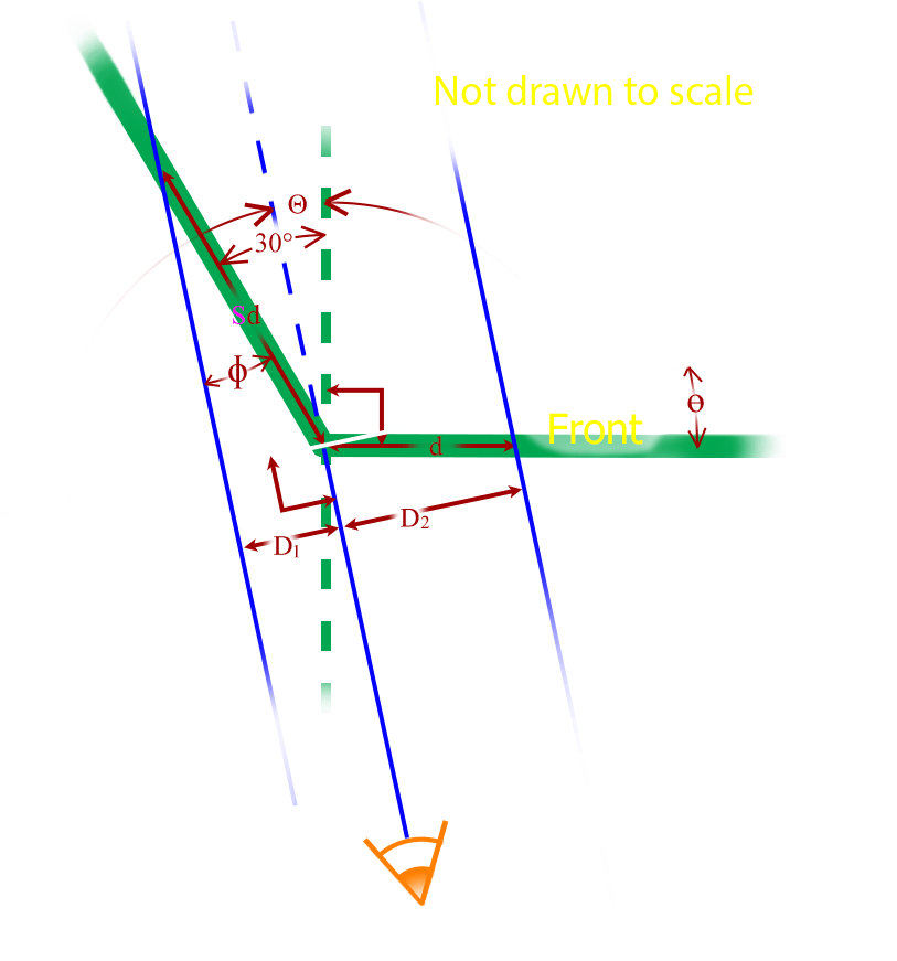
Finding The Illusion Angle Θ For A 30° Bevel
Again, this analysis assumes that you are viewing this image from far enough away that the parallax, or difference in the angle of the light rays (shown in blue) from the various parts of the image to your eye is insignificant (meaning all of the blue lines look almost parallel). The white line in the picture represents a plane parallel to your eye's retina or perpendicular to the blue light rays coming from the image. It is actually just an imaginary construction line conveniently placed so that we can compare the apparent distances (as you see them) of two points that would have been equally distant from the corner of the image had we not stretched one side. This construction line is also placed against the corner of the image so that we can measure the appropriate angles. The green lines represent the canvas that we are viewing. In this exercise we are trying to find the angle Θ so that the distance D1 on the left side (which is how the distance Sd appears to your eye) will look the same as distance D2 on the right (representing your perspective of the distance d on the face of the frame). The more general "S", for stretch factor or stretch ratio, replaces the magenta 4 (representing how much I usually stretch that section) from our previous discussion so that it can be isolated later. After solving for Θ, we will explore how the angle of illusion Θ changes as we stretch the margins different amounts (meaning with different values of S). Finally we will work the relationship in reverse and find what stretch ratio we need to create a given illusion angle. All angles will be in degrees. In this case, the bevel angle is 30°. We will generalize in the final section.
| equations | comments |
| D2/d = cos(Θ) | small triangle relationships |
| Φ = 30°-Θ | angle relationships |
| D1/Sd = sin(Φ) = sin(30°-Θ) = cos(60°+Θ) | large triangle relationships |
| D ≝ (D1 = D2) | defined only at the illusion angle |
| Sd ∙ sin(30°-Θ) = d ∙ cos(Θ) | substitution |
| sin(30°-Θ) / cos(Θ) = 1/S | algebraic manipulation to isolate D |
| sin(30°-Θ) = sin(30°) cos(Θ) - cos(30°) sin(Θ) | trigonometric identity |
| (sin(30°) cos(Θ) - cos(30°) sin(Θ)) / cos(Θ) = sin(30°) - cos(30°) tan(Θ) | substitution |
| sin(30°) - cos(30°) tan(Θ) = 1/S | " " |
| tan(Θ) = (sin(30°) - 1/S) / cos(30°) | " " |
| sin(30°) = ½, cos(30°) = sqrt(3)/2 | properties of 30-60-90° triangle |
| Θ = tan-1((1 - 2/S) / sqrt(3)) | solve for Θ |
Consequences Of Different Stretch Factors
To find the angle for for a particular amount of stretch, all you have to do is change the S in the equations with the desired stretch ratio. For example, if you want to stretch that margin four times (giving a 4:1 ratio), you would replace the S in that last equation with 4. In the below table I've done that and calculated the answer for the nice round ratios. The ratio of 1:1 represents the case of no stretching, just wrapping. The resulting negative 30° angle means you are standing to the side of the picture, not in front of the picture. That answer should not be a surprise.
| Stretch Ratio (S) | Illusion Angle (Θ) |
|---|---|
| 8:1 | 23.4° |
| 7:1 | 22.4° |
| 6:1 | 21.1° |
| 5:1 | 19.1° |
| 4:1 | 16.1° |
| 3:1 | 10.9° |
| 2:1 | 0° |
| 1:1 | -30° |
The Stretch Factor (S) Needed For A Particular Illusion Angle (Θ)
Starting with the fifth equation in the above solution:
| equations | comments |
| Sd ∙ sin(30°-Θ) = d ∙ cos(Θ) | |
| S ∙ sin(30°-Θ) = cos(Θ) | remove d from both sides |
| S = cos(Θ) / sin(30°-Θ) | solve for S |
What About Other Bevels?
First, we can solve for the illusion angle Θ by substituting the generic bevel angle β for 30° in the third line from the bottom of the section for the 30° solution for Θ above:
tan(Θ) = (sin(β) - 1/S) / cos(β).
Then we will use a 45° bevel, which we are also experimenting with, as an example of the process:
| equations | comments |
| tan(Θ) = (sin(45°) - 1/S) / cos(45°) | " " |
| sin(45°) = cos(45°) = sqrt(2)/2 | properties of 30-60-90° triangle |
| Θ = tan-1(1 - sqrt(2)/S) | solve for Θ |
This would result in the following illusion angles:
| Stretch Ratio (S) | Illusion Angle (Θ) |
|---|---|
| 8:1 | 39.5° |
| 7:1 | 38.6° |
| 6:1 | 37.4° |
| 5:1 | 35.6° |
| 4:1 | 32.9° |
| 3:1 | 27.9° |
| 2:1 | 16.3° |
| 1:1 | -22.5° |
By the same token, the generic form of the stretch factor equation would be S = cos(Θ) / sin(β-Θ). For our 45° bevel, this turns into S = cos(Θ) / sin(45°-Θ).
I will soon write an a blog article giving an example of how to use these equations to process the canvas print of an image for a beveled-edge frame in order to create an optimal illusion viewing distance, a point at which all four edges are visible and look like an uncompressed and unstretched continuation of the front image (see How To Make Your Beveled Edges Look Like A Continuation Of Your Image).
If you have any questions about any of this, you can contact us. Hit the Comment Button below if you have any suggestions for improvement.