And More . . .
We found that when using moulding with 45° bevels, there isn’t much extra material to work with when trying to make the corner folds while stretching the canvas. Thirty-degree bevels aren’t as bad, so that is what we usually use for stretching our images. I’ve also found that on those images with a high aspect ratio (meaning a large relative difference between the height and width of the image), as happens in panoramas, it is hard finding an “illusion viewing angle” (as described in How To Make Your Beveled Edges Look Like A Continuation Of Your Image), common to both the horizontal and vertical edges. For that reason, we have started using the 45°-beveled moulding on the short edges of our panoramas and 30° bevels on the long sides. That helps solve both problems; folding the corners is easier than using just 45° bevels and we can still find a common illusion viewing distance. But how does one cut the miters?
I recently published a blog postarticle making this question into a contest. With the publishing of this article, that contest is officially over. As that post mentions, I will soon announce any winners in its comment section.
The Specs
Plan A
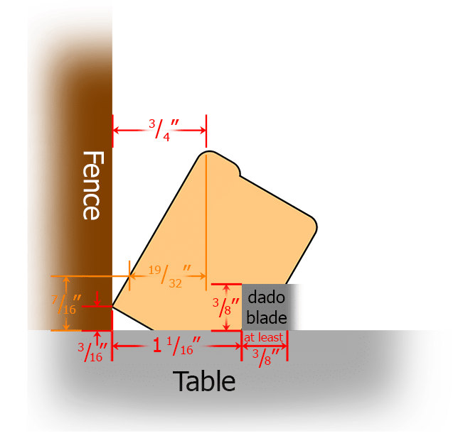
I knew that the only important areas, which had to line up exactly, were the outer slopes where the canvas was stretched around the edge and stapled on the back/bottom face. Based on the information in Figure 1, I came up with a plan. In Figure 2 we can see that the miter angle is
\( arctan(\frac{\frac{3}{4}}{1 \frac{1}{16}}) = 35.2^{\circ} \)
An Angle Warning
As I mentioned in Using Multiple Moulding Widths In One Frame, you need to be careful in calculating and labeling angles. You need to keep track of which measurement should go on the bottom of the fraction when calculating the tangent. You also need to be aware that your equipment might not be using the same reference line you are when describing angles. Click on the above link to review those warnings.
Graphical Solution
As much as I love math, it should be pointed out that trigonometry isn’t strictly required for this process. You can solve this problem graphically. As one professional framer (Wally Fay CPF) mentioned in his comments to Using Multiple Moulding Widths In One Frame, you can “cut the four lengths just over their final length and make a cardboard template of the finished product (or, using the appropriate measurements, make a scale drawing of the corner, like the ones in Figures 2 & 4). Using a sliding T-bevelvideo, transfer the cut angles for the miters to your saw from the template”. If you don’t have a sliding T-bevel, you can use a protractor, but the precision will suffer a bit.
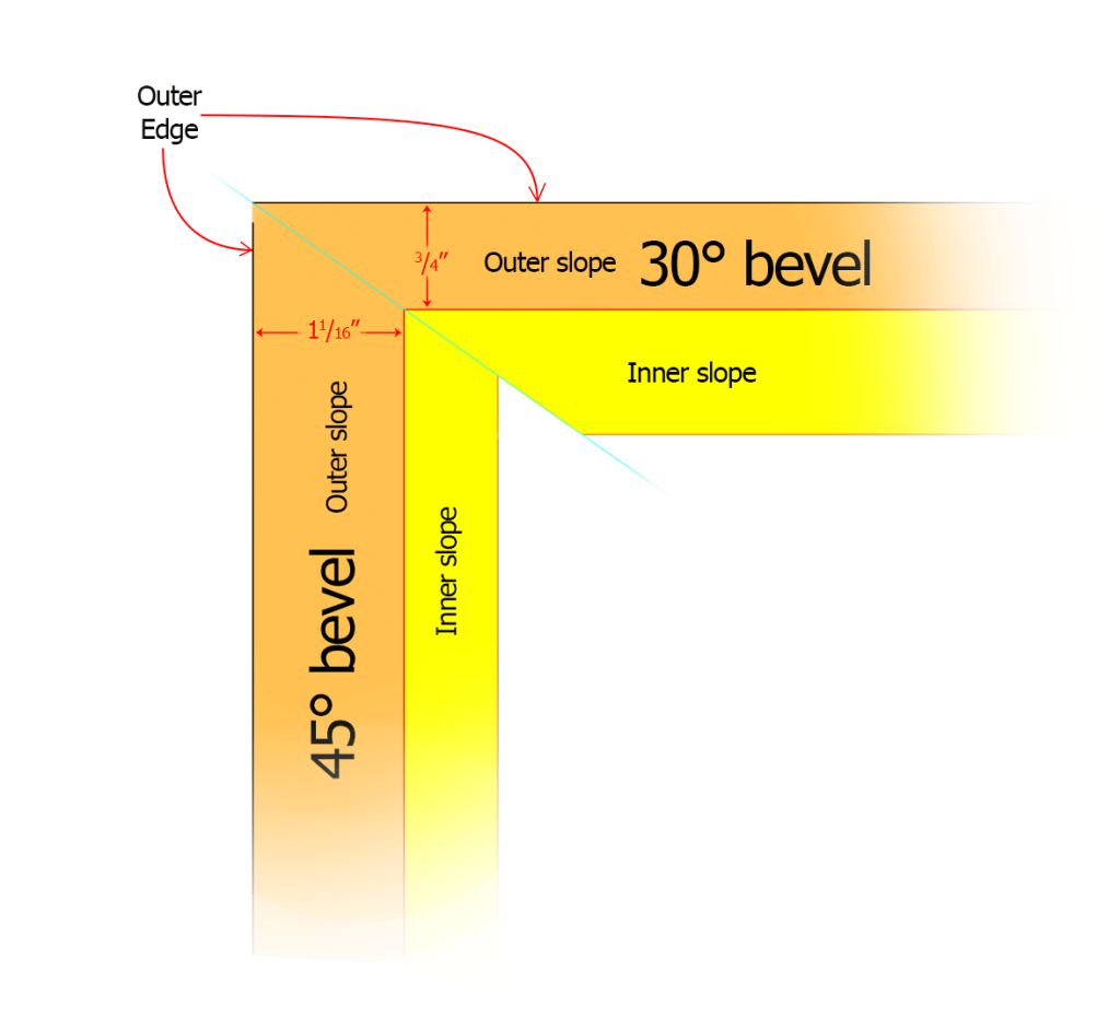
Suppose you want to make a frame for an 18″ by 36″ print on canvas. In Figure 2, your image for the front face would cover and come to the edge of the inner slope (shown in yellow). To find the overall moulding width for the 30°-beveled moulding, which would be along the long edge (36″), you would add the width of the outer slope (shown in orange) of the 45° moulding (11/16“) to each end to find the cut length along the outside edge of the wood. In this case that would be 381/8“. By the same token, the length of the 45° pieces would be 18” + (2 x 3/4“) = 191/2“.
Unfortunately, I overlooked one detail. Figure 3 shows the result. From above, it looks perfect . . .

Plan B: success
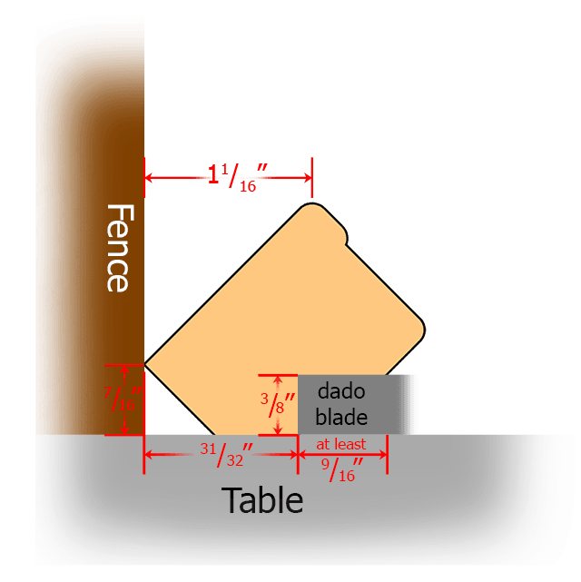
. . . but it doesn’t mean anything to match the maximum width; one must match the width at every common elevation. This means we have to match widths at every height from the top until the 45°-bevel face turns under (7/16″ above the ground, as shown in Figure 1). At that height, the width of the outer slope of the 30° bevel is only
\( \frac{3}{4}” \cdot \frac{(1 \frac{1}{2} – \frac{7}{16})}{(1 \frac{1}{2} – \frac{3}{16})} = 0.60714 \approx \frac{19}{32}” \)
(also shown in Figure 1) which makes the true miter angle
\( \arctan(\frac{\frac{19}{32}}{1 \frac{1}{16}}) = 29.7^{\circ} \)
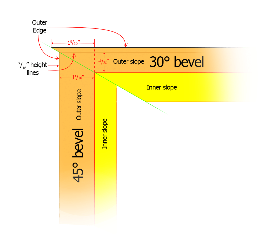
In this case, for our same 18″ by 36″ print, you would need to add 15/16” to both sides of the 30°-beveled moulding (which is longer than the outer-slope width of the 45° moulding) to make the overall length 385/8“. To the 45° moulding, you would add two times 19/32“. (That measurement is less than the outer slope distance of the 30°-beveled moulding.) The total length would then be 193/16“. The finished overall/outside measurements (for shipping purposes, perhaps) can still be found by just adding the appropriate outer slope widths to each end (giving 381/8” and 191/2“. This is the same answer as you would have gotten using Plan A.)
A Small Angle Problem
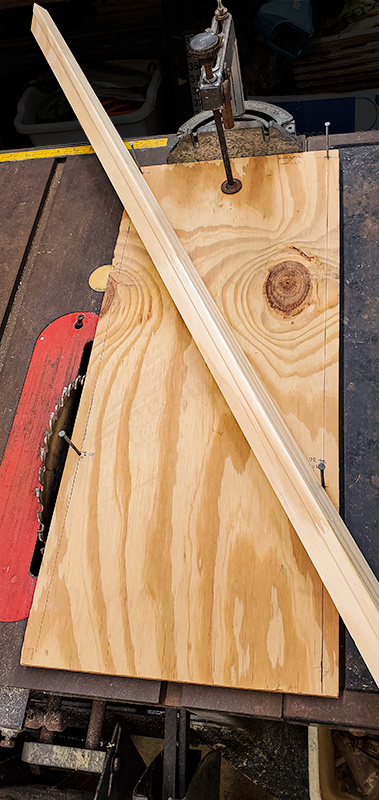
We don’t have a single tool that can be used to cut miters less than 30° (neither radial arm saw, miter saw (see Figure 4B in ‘Using Multiple Moulding Widths In One Frame’), or table saw (notice miter gauge in Figure 5A below). So this time I made a crude sled jig because the method I used last timelink gets awkward for long pieces. On a piece of plywood, I marked a baseline just inside the short edge next to the miter gauge and a perpendicular line just inside each long edge. I measured the distance along the baseline between those two parallel lines (millimeters is probably best for this because they are small and need no fractional conversions), call it “W”, and pounded a nail where each of them intersects the baseline. Then I measure a length L along both long edges, according to the below formula, and pound in another nail.
\( L = \frac{W}{\tan(29.7^{\circ})} \)
My Jig
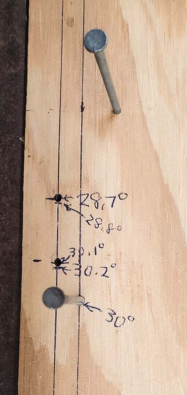
Figure 5A shows Version 1 of this jig. Figure 5B shows a closeup of one edge of the jig after we enhanced it with a second set of parallel lines (with a different W), so the nails for similar cuts don’t have to be so close. We added the second nail at the top of that figure just to help hold the moulding in place. (Figure B is actually upside down relative to figure A to make the numbers easier to read.)
[3/18/2023: You may also want to check out a short video by Casey Finn on Instagram that I just ran across. See Angled Miter Cut. (I have not yet tested this setup.)]
As you can see in Figure 4, although this plan should match the edges of the two pieces exactly, from the peak, along the outer edge, until the 45° moulding turns underneath, it does create a little projection on the 30° moulding. This should be removed before gluing and using the band clamp.
Results
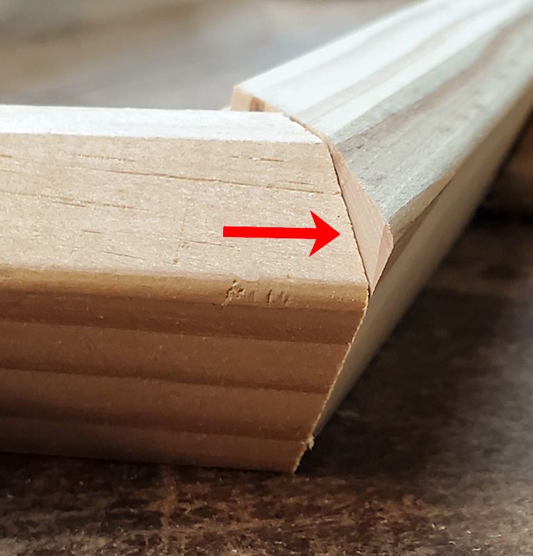
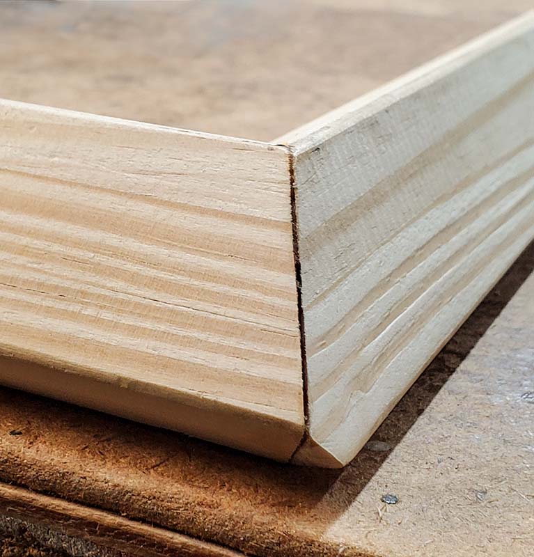
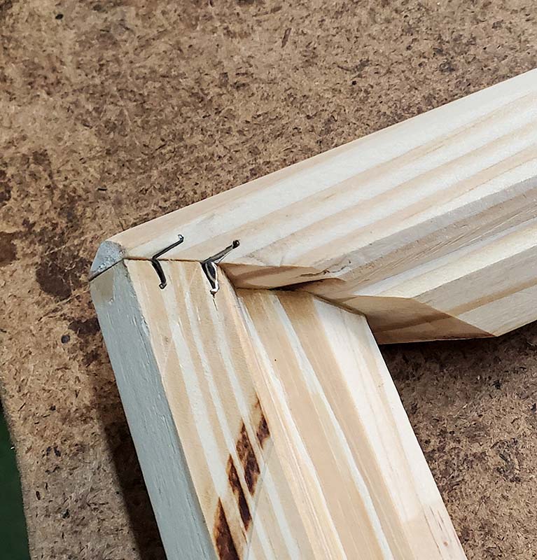
Figure 6 shows the results of the cuts. Photo A shows the corner, bottom side up. You can see the projection on the 30° moulding (to the right), adjacent to what would be the lower, inner-sloping face of the 45° moulding. An adjacent corner is in Photo B with the front face up after the projection was sawed/filed off and the pieces glued. (The 30° bevel is again on the right.) Photo C again shows the bottom of the frame (similar corner to Photo B), after V-nailing.
Bonus Solution: Joining Mouldings With 30° & 0° Bevels
Since I mentioned it in the Note in “The Challenge” section of A Contest For Woodworkers: Make Miter Cut Between Differently-beveled Mouldings, I’ll give you the information on joining a regular no-bevel piece of moulding with one having a 30° bevel as another example of this issue.
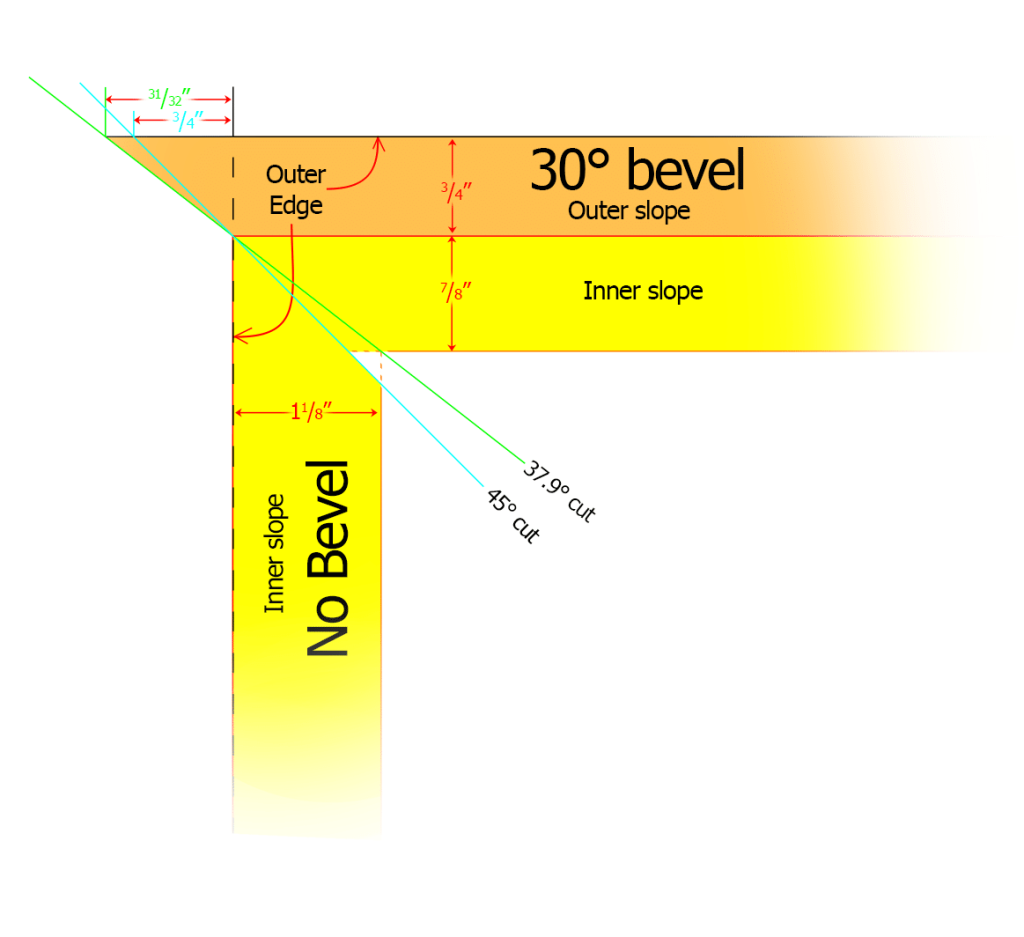
The short answer is that you can cut the miter at whatever angle you like (as long as the angles of the two cuts are complementary (their sum is 90°) and you line up the outside edge of the regular moulding with the peak of the 30° moulding as shown in Figure 7. In any case, you will have a large projection on the 30° moulding that extends past the regular moulding. Again, this needs to be removed before gluing and clamping. The simplest answer would be regular 45° miters, but the inner edges won’t be quite as tidy. If you put a
\( 37.9^{\circ} \mbox{ (= } \arctan(\frac{\frac{7}{8}}{1 \frac{1}{8}}) ) \)
cut on the 30°-beveled piece, it should give you more gluing surface.
Back to our 18″ by 36″ example, and saying the regular, non-beveled moulding will be on the short side of the image, you would add either 31/32” or 3/4” to each end of the 36″ piece, depending on whether you made the 37.9° miter cut or the 45° cut, respectively. This means the cut length will be either 3715/16” or 371/2“. For the non-beveled 18″ pieces, you would add nothing to both ends, regardless of which miter cut you made. The final overall lengths, after again adding the appropriate outer-slope widths of the opposite pieces, would be 36” and 191/2“.
Trimming The Regular (non-beveled) Moulding (Optional)
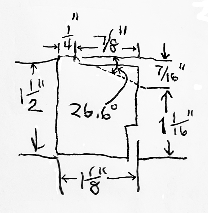
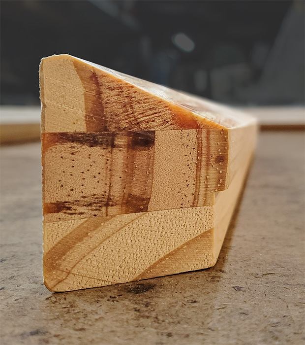
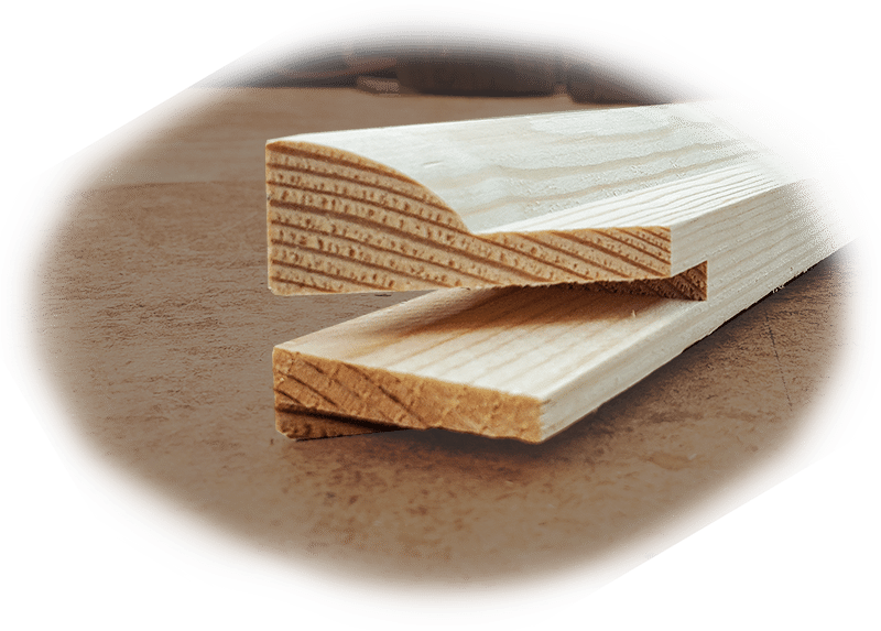
When joining non-beveled moulding to moulding with a 30° bevel, I trim the top of the non-beveled moulding to better match the inner slope of the adjacent moulding. Figure 8A shows the specifications, while Figure 8B shows the finished moulding.
Results
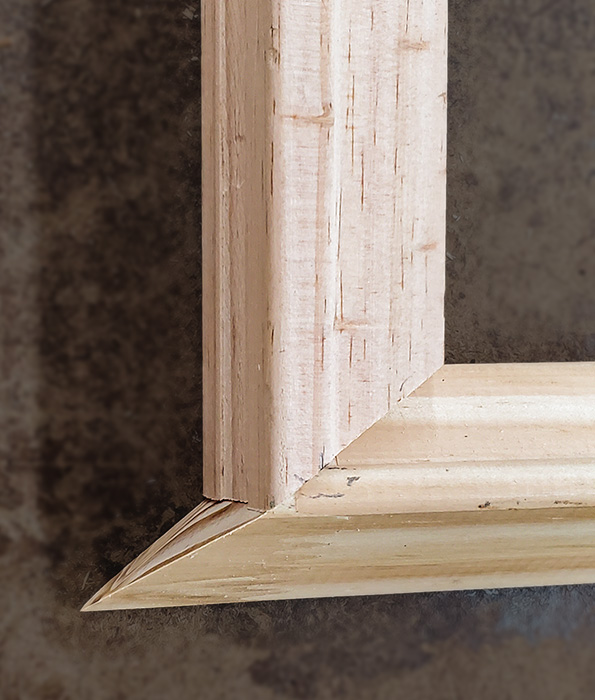
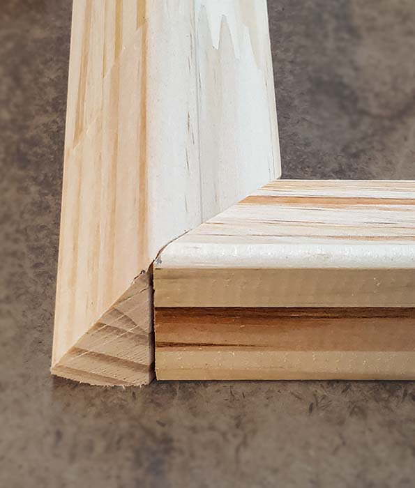
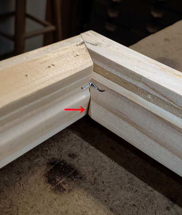
Figure 9A shows a corner using the 37.9° miter cut on the 30°-beveled moulding (along the bottom edge of the picture). The projection is clearly visible. Figure 9B shows a different corner (with the 30°-beveled moulding on the left) after we removed the projection. This joint used a 45° miter cut, although the gap/notch on the inside corner isn’t as visible from this perspective. It shows up a little better at the bottom of the miter (follow arrow below the lower staple) in Figure 9C, which shows another 45° mitered corner (with the 30°-beveled piece on the right), bottom side up, after being glued and nailed (by hand).
What’s Next
Stretcher vs. Strainer
Although the term “stretcher frame” has almost become generalized to include both types, some commenters to my contestlink have correctly pointed out there is a difference between a canvas stretcher frame and a strainer frame (see “Stretcher or strainer?”). What we’ve described and have been working with so far have been stainer frames. It is easy to cut them to any length and assemble them the same as any other picture frame.
True Stretcher Frames
Stretcher frame corners are more complicated. As you can see, they have mortises and tenons. Tenons are the wide, but thin projecting components that fit into the matching mortise or slot in the adjacent piece. These components are all parallel to the same plane. The pieces are assembled snugly without nails or glue so that the frame can expand, but only within that plane. Making these corners is best done with special tools and is well beyond the scope of this article. Store-bought stretcher bars come premade in specific lengths that are all multiples of whole inches. For a debate on whether or not you need to use proper stretcher bars, see The Picture Framers Grumble: To Key or Not to Key… .
My technique for putting the bevel on the bars will not work with these stretcher bars. It will tilt the moulding, causing the tenons and the matching mortises to be on different planes. That means they will no longer fit together. Again, some of the forum commenters had suggestions that might lead to an easier technique that could work on both strainer and stretcher bars. I’ve already purchased the materials I need to develop and test those ideas. If successful, I will pass that information on to you. In the meantime, I need to address other promises and projects (like the rock printing project). Stay tuned.
Leave a Reply